
Core drilling tools compatibility requires the exact rod, thread, barrel, bit and retrieval-system specifications, plus their load and operating limits. Nominal size and physical fit are insufficient. Identify existing parts, verify each mating interface and obtain written confirmation of the complete assembly before ordering replacements.
Identify the standard, product family and component revision
Record the manufacturer, full system designation, part number, revision, dimensions and condition of each retained component. Preserve suffixes that distinguish barrel variants or rod constructions. A purchasing description such as “N-size tools” leaves too much unspecified.
ISO 3551-1:1992 covers System A rotary core diamond-drilling equipment, including rods, casings, barrels and cutting components. Its public scope specifies hole diameters from 30 to 200 mm; it does not certify an unidentified aftermarket assembly. Read the ISO standard’s scope.
If a quotation claims compliance with a standard, ask which parts and dimensions it covers and what evidence is supplied. Keep the referenced standard and manufacturer drawing together in the purchase record.
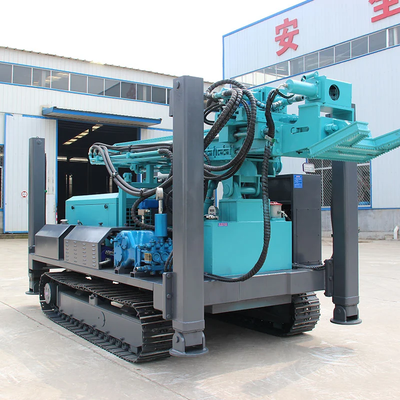
Verify core, bit and barrel dimensions separately
Verify the core diameter, bit outside diameter and internal barrel arrangement separately for the specified system, including variants such as HQ and HQ3. Matching the outer cutting diameter does not identify the internal sample system or confirm component compatibility.
| Interface | Identification required |
|---|---|
| Drive sub to rods | Thread designation, shoulder geometry and applicable torque limits. |
| Rod to rod | Product family, full connection drawing, condition and make-up requirements. |
| Rod to barrel | Couplings, mating threads, internal clearances and fluid path. |
| Barrel to bit and reaming shell | Exact barrel variant, gauge, thread and component part numbers. |
| Inner tube to retrieval assembly | Head, latch, spearhead, overshot and tube identity. |
| Casing and hole program | Casing sequence, hole and component dimensions, and required clearances for the approved assembly. |
| External fluid supply | Swivel, hoses, connections and fluid-delivery interfaces, with each supply responsibility identified. |
Ask the supplier to mark the proposed components on an assembly drawing. Dimensions copied from different catalogues should not be treated as proof that the resulting assembly has been reviewed.
Check the latch and retrieval interfaces as functional components
Check the latch-seat design and coupling arrangement for the exact product family and revision. A design change may alter mating components and engagement; a familiar system name is not a blanket statement of interchangeability.
A replacement may share an external size while differing in latch engagement, clearance, release or fluid behaviour. Identify the head assembly and overshot together. Follow the applicable manufacturer’s restrictions on mixing rods, couplings, adapters and retrieval components; do not treat physical fit as approval for a mixed assembly.
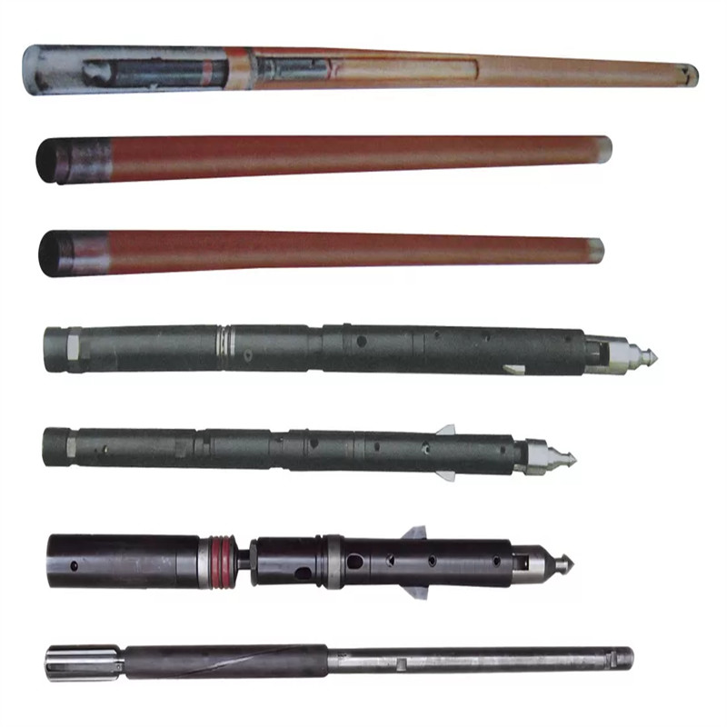
Specify inspection or functional verification according to the applicable manual. Do not use a visual fit or a partly engaged thread as acceptance. Keep worn, modified or unidentified parts out of the approved assembly until they are assessed.
Compare component limits with the actual rig configuration
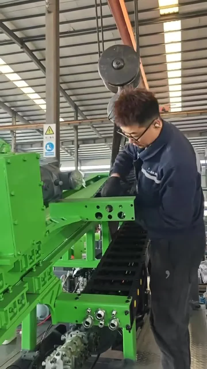
The dragondrill DR-1000X page lists a maximum torque of 2,600 N·m. This machine field does not establish the allowable make-up torque, operating torque or pulling load of every attached rod or adapter. Review the DR-1000X specification.
Ask for the applicable limits for the drive, rods, couplings, barrel and handling equipment. Confirm the operating speed and loading conditions as well as the connection drawing. Any adapter introduces interfaces that need the same review.
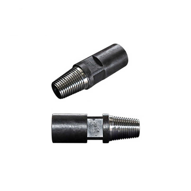
Check worn stock against the manufacturer’s inspection criteria. A new replacement part does not restore the rating of a damaged mating component. Use the depth-capacity guide to keep the rig rating linked to the named drill string.
Put the approved assembly and permitted substitutions into the order
Specify the retrieval architecture: identify the sample-bearing inner-tube group, its relationship to the rod string and the matching overshot. Keep the component identities and approved assembly relationships together in the order.
Create an order schedule that names each supplied component, quantity, matching retained part and supporting drawing. Ask the supplier to state any exceptions. Require proposed substitutions to identify the changed interfaces and receive the agreed technical approval before dispatch.
For replacement orders, include photographs of markings and measurements, the original documentation where available, and the symptoms or wear that prompted replacement. Do not infer the part solely from a machine model.
Receipt and service-parts checks
- Match component markings to the approved assembly and purchase references.
- Reconcile packing-list detail with the identified components and quantities, including separately packed interfaces.
- Retain the agreed inspection documents with the assembly drawings and their revisions.
- Link the service-parts list to the approved assembly so a later replacement order preserves its component identities and approved interfaces.
Send that identification package to request a core drilling tools compatibility review. If the retrieval method is also changing, include the wireline versus conventional system requirements.
Frequently asked questions
Are core drilling tools with the same NQ or HQ size label interchangeable?
Not automatically. Identify the manufacturer, complete product designation, threads, barrel variant and retrieval parts. Verify dimensional and functional compatibility, applicable loads and the condition of retained parts. A shared nominal size is not a written approval of the complete assembly.
Why can two core bits with the same outside diameter produce different core diameters?
They can belong to different barrel and internal sample systems. Variants such as HQ and HQ3 must be identified separately. Specify both core and bit outside diameters and the exact system from the applicable drawing; a shared outer diameter does not confirm the same internal sample arrangement.
Does ISO 3551 compliance mean any supplier’s core tools will fit my drill string?
No. ISO 3551-1 addresses defined equipment and leading dimensions within System A. Ask which supplied components comply and obtain the applicable drawings. Complete assembly compatibility and operating limits still need confirmation.
What should I send when requesting replacement wireline core barrel parts?
Send manufacturer and part markings, full system designation, dimensions, photographs, existing assembly documents and the parts to be retained. Identify the head, latch and overshot together. Ask for a written replacement list and any required mating-component changes.